The IP Security (IPsec) protocol provides a framework for configuring secure VPNs and is commonly deployed over the Internet to connect branch offices, remote employees, and business partners. It is a reliable way to maintain communication privacy while streamlining operations, reducing costs, and allowing flexible network administration.
IPSec VPN negotiation can be broken down into five steps
Step 1. An IPsec tunnel is initiated when Host A sends “interesting” traffic to Host B. Traffic is considered interesting when it travels between the IPsec peers and meets the criteria that is defined in the crypto access control list (ACL).
Step 2. Router1 and Router2 negotiate a Security Association (SA) used to form an IKE Phase 1 tunnel, which is also known as an ISAKMP tunnel.
Step 3. Within the protection of the IKE Phase 1 tunnel, an IKE Phase 2 tunnel is negotiated and set up. An IKE Phase 2 tunnel is also known as an IPsec tunnel.
Step 4. After the IPsec tunnel is established, interesting traffic flows through the protected IPsec tunnel
Step 5. After no interesting traffic has been seen for a specified amount of time, or if the IPsec SA is deleted, the IPsec tunnel is torn down.
Elements of a site-to-site VPN:
+ Headend VPN device: Acts as a VPN termination device, located at a primary network location (for example, a headquarters location)
+ VPN access device: Serves as a VPN termination device, located at a remote office
+ Tunnel: Provides a logical connection over which traffic flows (for example, an IP Security [IPsec] tunnel and/or a Generic Router Encapsulation [GRE] tunnel)
+ Broadband service: Transports traffic to and from the Internet (for example, over a cable or DSL connection)
Now you understand the fundamental of IPsec site-to-site VPN. In summary, the site-to-site VPN requires Internet or other common environments as the transport so security is the primary concern and this can be protected by IPsec. IPsec operates at Layer 3 of the OSI model (Network layer) and it is independant of the applications. It means that the applications don’t require any modifications to use IPsec.
IPsec Modes
IPsec uses 2 modes to establish a secure communication channel between network nodes, Transport mode & Tunnel mode. These 2 modes are different in what parts of IP headers and payloads are to be kept confidential. In Transport mode, security is provided only for the transport layer and above while Tunnel mode will encapsulate the original IP header and creates a new IP header that is sent unencrypted across the untrusted network.
IPsec Transforms
IPsec delivers data confidentiality services by executing a “transform” on plain text data into a block of ciphertext. Common ciphers used in the IPsec transforms are DES, 3DES, and AES. 3DES and AES are considered to be stronger encryption ciphers than DES, as they use longer encryption keys (128-bit key for 3DES and 256-bit key for AES).
Note:
Confidentiality ensures that only authorized individuals can view sensitive data. Powerful methods of ensuring confidentiality are encryption and access controls.
Integrity ensures that data has not been changed by an unauthorized individual.
Availability ensures that access to the data is uninterrupted. Denial-of-service (DoS) attacks attempt to compromise data availability. These attacks typically try to fail a system using an unexpected condition or input, or fail an entire network with a large quantity of information.
IPSec - Internet Protocol Security
|
How IPSec works
The Internet Security Agreement/Key Management Protocol and Oakley ( ISAKMP)
ISAKMP provides a way for two computers to agree on security settings and exchange a security key that they can use to communicate securely. A Security Association (SA) provides all the information needed for two computers to communicate securely. The SA contains a policy agreement that controls which algorithms and key lengths the two machines will use, plus the actual security keys used to securely exchange information.
There are two steps in this process. First, the two computers must agree on the following three things:
1) The encryption algorithm to be used (DES, triple DES)
2) Which algorithm they'll use for verifying message integrity (MD5 or SHA-1)
3) How connections will be authenticated: using public-key certificate, a shared secret key or Kerberos.
Once all that has been sorted out, they start another round of negotiations which cover the following:
1) Whether the Authentication Header (AH) protocol will be used
2) Whether the Encapsulating Security Payload (ESP) protocol will be used
3) Which encryption algorithm will be used for ESP
4) Which authentication protocol will be used for AH
IPSec has 2 mechanisms which work together to give you the end result, which is a secure way to send data over public networks. Keep in mind that you can use both or just one of these mechanisms together.
These mechanisms are:
1) Authentication Header
2) Encapsulating Security Payload - ESP
The Authentication Header (AH) Mechanism
The Authentication Header information is added into the packet which is generated by the sender, right between the Network (Layer 3) and Transport (Layer 4) Layer (see picture below).
Authentication protects your network, and the data it carries, from tampering. Tampering might be a hacker sitting between the client and server, altering the contents of the packets sent between the client and server, or someone trying to impersonate either the client or server, thus fooling the other side and gaining access to sensitive data.
To overcome this problem, IPSec uses an Authentication Header (AH) to digitally sign the entire contents of each packet. This signature provides 3 benefits:
1) Protects against replay attacks. If an attacker can capture packets, save them and modify them, and then send them to the destination, then they can impersonate a machine when that machine is not on the network. This is what we call a replay attack. IPSec will prevent this from happening by including the sender's signature on all packets.
2) Protection against tampering. The signatures added to each packet by IPSec means that you can't alter any part of a packet undetected.
3) Protection against spoofing. Each end of a connection (e.g client-server) verifies the other's identity with the authentication headers used by IPSec.
The AH is computed on the entire packet, including payload (upper layers - 4,5,6,7) and headers of each layer. The following picture shows us a packet using AH :
Below is the analysis of the Authentication Header.
AH Algorithms
For point-to-point communication (e.g client to server), suitable authentication algorithms include keyed Message Authentication Codes (MACs) based on symmetric encryption algorithms (e.g DES) or on one-way hash functions (e.g MD5 or SHA-1).
For multicast communication (e.g between a group of routers), one-way hash algorithms combined with asymmetric signature algorithms are usually used, but they are also more cpu intensive.
The Encapsulating Security Payload - ESP
The Authentication Header (AH) we spoke about will protect your data from tampering, but it will not stop people from seeing it. For that, IPSec uses an encryption which provides the Encapsulating Security Payload (ESP). ESP is used to encrypt the entire payload of anIPSec packet (Payload is the portion of the packet which contains the upper layer data).
ESP is a bit more complex than AH because alone it can provide authentication, replay-proofing and integrity checking. It acomplishes this by adding 3 separate components:
1) An ESP header
2) An ESP trailer and
3) An ESP authentication block.
Each of these components contains some of the data needed to provide the necessary authentication and integrity checking. To prevent tampering, an ESP client has to sign the ESP header, application data, and ESP trailer into one unit, of course ESP is used to encrypt the application data and the ESP trailer to provide confidentiality. The combination of this overlapping signature and encryption operation provides good security.
Let's have a look at a packet using IPSec - ESP:

Understanding IPSec Modes –Tunnel Mode & Transport Mode
IPSec can be configured to operate in two different modes, Tunnel and Transport mode. Use of each mode depends on the requirements and implementation of IPSec.
IPSec Tunnel Mode
IPSec tunnel mode is the default mode. With tunnel mode, the entire original IP packet is protected by IPSec. This means IPSec wraps the original packet, encrypts it, adds a new IP header and sends it to the other side of the VPN tunnel (IPSec peer).
Tunnel mode is most commonly used between gateways (Cisco routers or ASA firewalls), or at an end-station to a gateway, the gateway acting as a proxy for the hosts behind it.
Tunnel mode is used to encrypt traffic between secure IPSec Gateways, for example two Cisco routers connected over the Internet via IPSec VPN. Configuration and setup of this topology is extensively covered in our Site-to-Site IPSec VPN article. In this example, each router acts as an IPSec Gateway for their LAN, providing secure connectivity to the remote network:

Another example of tunnel mode is an IPSec tunnel between a Cisco VPN Client and an IPSec Gateway (e.g ASA5510 or PIX Firewall). The client connects to the IPSec Gateway. Traffic from the client is encrypted, encapsulated inside a new IP packet and sent to the other end. Once decrypted by the firewall appliance, the client’s original IP packet is sent to the local network.
In tunnel mode, an IPSec header (AH or ESP header) is inserted between the IP header and the upper layer protocol. Between AH and ESP, ESP is most commonly used in IPSec VPN Tunnel configuration.
The packet diagram below illustrates IPSec Tunnel mode with ESP header:
ESP is identified in the New IP header with an IP protocol ID of 50.
The packet diagram below illustrates IPSec Tunnel mode with AH header:
The AH can be applied alone or together with the ESP, when IPSec is in tunnel mode. AH’s job is to protect the entire packet. The AH does not protect all of the fields in the New IP Header because some change in transit, and the sender cannot predict how they might change. The AH protects everything that does not change in transit. AH is identified in the New IP header with an IP protocol ID of 51.
IPSec Transport Mode
IPSec Transport mode is used for end-to-end communications, for example, for communication between a client and a server or between a workstation and a gateway (if the gateway is being treated as a host). A good example would be an encrypted Telnet or Remote Desktop session from a workstation to a server.
Transport mode provides the protection of our data, also known as IP Payload, and consists of TCP/UDP header + Data, through an AH or ESP header. The payload is encapsulated by the IPSec headers and trailers. The original IP headers remain intact, except that the IP protocol field is changed to ESP (50) or AH (51), and the original protocol value is saved in the IPsec trailer to be restored when the packet is decrypted.
IPSec transport mode is usually used when another tunneling protocol (like GRE) is used to first encapsulate the IP data packet, then IPSec is used to protect the GRE tunnel packets. IPSec protects the GRE tunnel traffic in transport mode.
The packet diagram below illustrates IPSec Transport mode with ESP header:
Notice that the original IP header at the front is the IP header from the original IP packet. Placing the sender’s IP header at the front (with minor changes to the protocol ID), proves that transport mode does not provide protection or encryption to the original IP header and ESP is identified in the New IP header with an IP protocol ID of 50.
The packet diagram below illustrates IPSec Transport mode with AH header:
The AH can be applied alone or together with the ESP when IPSec is in transport mode. AH’s job is to protect the entire packet, however, IPSec in transport mode does not create a new IP header in front of the packet but places a copy of the original with some minor changes to the protocol ID therefore not providing essential protection to the details contained in the IP header (Source IP, destination IP etc). AH is identified in the New IP header with an IP protocol ID of 51.
In both ESP and AH cases with IPSec Transport mode, the IP header is exposed.
Dynamic Multipoint VPN (DMVPN) Deployment Models & Architectures
DMVPN Deployment Models
Following are the most popular DMVPN deployment models found in over 85% of DMVPN networks across the globe:
- Single DMVPN Network/Cloud - Single Tier Headend Architecture
- Single DMVPN Network/Cloud - Dual Tier Headend Architecture
- Dual DMVPN Network/Cloud – Single Tier Headend Architecture
- Dual DMVPN Network/Cloud – Dual Tier Headend Architecture
In every case a complete DMVPN deployment consists of the following services, also known as control planes:
- Dynamic Routing (Next Hop Resolution Protocol)
- mGRE Tunnels
- Tunnel Protection – IPSec Encryption that protects the GRE tunnel and data
Single DMVPN Network/Cloud - Single Tier Headend Architecture
This deployment model is DMVPN in its simplest form. It consists of the main Hub located at the headquarters and remote spokes spread amongst the remote offices.
The term ‘Single DMVPN’ refers to the fact there is only one DMVPN network in this deployment. This DMVPN network consists of the yellow GRE/IPSec Hub-and-Spoke tunnels terminating at the central Hub from one end and the remote spokes on the other end.
The term ‘Single Tier Headend’ means that all control planes are incorporated into a single router – the Hub. This means it takes care of the dynamic routing (NHRP), mGRE tunnels and IPSec Tunnel Protection.
The central hub maintains the Next Hop Resolution Protocol (NHRP) database and is aware of each spoke’s public IP address.
When setting up a DMVPN network, every spoke is configured, using static NHRP mappings, to register with the Hub. Through this process, every spoke is aware of every other’s public IP address via the NHRP server (Hub), no matter if the spokes IP addresses are dynamic or static.
Through DMVPN, each spoke is able to dynamically build a VPN tunnel to each other spoke, allowing the direct communication between them without needing to tunnel all traffic through the main Hub. This saves valuable bandwidth, time and money.
We should at this point note that in Phase 1 DMVPN, all traffic passes through the Hub. Phase 2 and Phase 3 DMVPN, directly forms spoke-to-spoke tunnels and sends traffic directly, bypassing the Hub.
The Single DMVPN - Single Tier Headend Architecture has the advantage of requiring only one Hub router, however, the Hub’s CPU is also the limiting factor for this deployment’s scalability as it undertakes all three control planes (NHRP, mGRE & IPSec protection).
In addition the Hub router, and its link to the Internet, is the single point of failure in this design. If any of the two (Hub or Internet link) fail, it can cripple the whole VPN network.
This DMVPN model is a usual approach for a limited budget DMVPN network with a few remote branches. Routing protocols are also not required when implementing a single DMVPN network/cloud. Instead, static routes can be used with the same end result.
Single DMVPN Network/Cloud - Dual Tier Headend Architecture
This DMVPN deployment consists of two routers at the headquarters. The first router, R1, is responsible for terminating the IPSec connections to all spokes, offloading the encryption and decryption process from the main Hub behind it. The Hub router undertakes the termination of mGRE tunnel, NHRP server and processing of all routing protocol updates.
The only real advantage offered by the Dual Tier Headend Architecture (Single DMVPN cloud) is that it can support a significantly greater number of spokes.
A limitation of Dual Tier Headend Architecture is the absence of the spoke-to-spoke connections, in Dual Tier DMVPN spoke-to-spoke connections are not supported.
Dual DMVPN Network/Cloud – Single Tier Headend Architecture
The Dual DMVPN topology with spoke-to-spoke deployment consists of two headend routers, Hub 1 and Hub 2. Each DMVPN network (DMVPN 1 & DMVPN 2) represents a unique IP subnet, one is considered the primary DMVPN while the other is the secondary/backup DMVPN.

The dynamic Spoke-to-Spoke tunnels created between branches must be within a single DMVPN network. This means that spoke-to-spoke tunnels can only be created between spokes in the same DMVPN network.
With Dual DMVPN – Single Tier Headend Architecture, each Hub manages its own DMVPN network. Each Hub undertakes the task of IPSec encryption/decryption, mGRE Tunnel termination and NHRP Server for its DMVPN network. A routing protocol such as EIGRP or OSPF is usually implemented in this type of setup to ensure automatic failover in case the primary DMVPN fails.
Dual DMVPN – Single Tier Architecture is considered an extremely flexible and scalable setup as it combines the best of both worlds – that is, true redundancy with two separate Hubs and DMVPN networks, plus support for spoke-to-spoke tunnels.
Dual DMVPN Network/Cloud – Dual Tier Headend Architecture
The Dual DMVPN Network – Dual Tier Headend combines the previous two deployment methods in one setup.
The Dual DMVPN Network – Dual Tier Headend consists of two Hubs that deal only with mGRE tunnels and NHRP services, each Hub managing its own DMVPN network.
Frontend routers R1 and R2 take care of all IPSec termination for all spokes, performing encryption/decryption as data enters or exits the IPSec tunnels.
Newer ISR G2 routers are capable of undertaking great quantities of number crunching for all VPN tunnels as they are equipped with hardware accelerated VPN modules that offload this process from the main CPU.
As with Dual DMVPN – Single Tier deployment model, each Hub manages its own DMVPN network and connections with its spokes. Routing protocols are a necessity to ensure automatic failover to the secondary DMVPN network in case the primary fails.
Unfortunately, as with all Dual Tier deployments, we lose the spoke-to-spoke ability, but this might not be a limitation for some.
Understanding Cisco Dynamic Multipoint VPN - DMVPN, mGRE, NHRP
Introduction to Cisco Dynamic Multipoint VPN - DMVPN
Dynamic Multipoint VPN (DMVPN) is Cisco’s answer to the increasing demands of enterprise companies to be able to connect branch offices with head offices and between each other while keeping costs low, minimising configuration complexity and increasing flexibility.
Note: Users familair with DMVPN can also visit our article Configuring Cisco Dynamic Multipoint VPN (DMVPN) - Hub, Spokes , mGRE Protection and Routing
With DMVPN, one central router, usually placed at the head office, undertakes the role of the Hub while all other branch routers areSpokes that connect to the Hub router so the branch offices can access the company’s resources. DMVPN consists of two mainly deployment designs:
- DMVPN Hub & Spoke, used to perform headquarters-to-branch interconnections
- DMVPN Spoke-to-Spoke, used to perform branch-to-branch interconnections
In both cases, the Hub router is assigned a static public IP Address while the branch routers (spokes) can be assigned static or dynamic public IP addresses. DMVPN combines multiple GRE (mGRE) Tunnels, IPSec encryption and NHRP (Next Hop Resolution Protocol) to perform its job and save the administrator the need to define multiple static crypto maps and dynamic discovery of tunnel endpoints.
DMVPN combines multiple GRE (mGRE) Tunnels, IPSec encryption and NHRP (Next Hop Resolution Protocol) to perform its job and save the administrator the need to define multiple static crypto maps and dynamic discovery of tunnel endpoints.
NHRP is layer 2 resolution protocol and cache, much like Address Resolution Protocol (ARP) or Reverse ARP (Frame Relay).
The Hub router undertakes the role of the server while the spoke routers act as the clients. The Hub maintains a special NHRP database with the public IP Addresses of all configured spokes.
Each spoke registers its public IP address with the hub and queries the NHRP database for the public IP address of the destination spoke it needs to build a VPN tunnel.
mGRE Tunnel Interface is used to allow a single GRE interface to support multiple IPSec tunnels and helps dramatically to simplify the complexity and size of the configuration.
Following is an outline of the main differences between GRE and mGRE interfaces:
A GRE interface definition includes:
- An IP address
- A Tunnel Source
- A Tunnel Destination
- An optional tunnel key
interface Tunnel 0
ip address 10.0.0.1 255.0.0.0
tunnel source Dialer1
tunnel destination 172.16.0.2
tunnel key 1
An mGRE interface definition includes:
- An IP address
- A Tunnel source
- A Tunnel key
interface Tunnel 0
ip address 10.0.0.1 255.0.0.0
tunnel source Dialer 1
tunnel mode gre multipoint
tunnel key 1
It is important to note that mGRE interfaces do not have a tunnel destination. Because mGRE tunnels do not have a tunnel destination defined, they cannot be used alone. NHRP fills this gap by telling mGRE where to send the packets.
DMVPN Benefits
DMVPN provides a number of benefits which have helped make them very popular and highly recommended. These include:
- Simplified Hub Router Configuration. No more multiple tunnel interfaces for each branch (spoke) VPN. A single mGRE, IPSec profile without any crypto access lists, is all that is required to handle all Spoke routers. No matter how many Spoke routers connect to the Hub, the Hub configuration remains constant.
- Full Support for Spoke Routers with Dynamic IP Addressing. Spoke routers can use dynamic public IP Addresses. Thanks to NHRP, Spoke routers rely on the Hub router to find the public IP Address of other Spoke routers and construct a VPN Tunnel with them.
- Dynamic Creation of Spoke-to-Spoke VPN Tunnels. Spoke routers are able to dynamically create VPN Tunnels between them as network data needs to travel from one branch to another.
- Lower Administration Costs. DMVPN simplifies greatly the WAN network topology, allowing the Administrator to deal with other more time-consuming problems. Once setup, DMVPN continues working around the clock, creating dynamic VPNs as needed and keeping every router updated on the VPN topology.
- Optional Strong Security with IPSec. Optionally, IPSecurity can be configured to provide data encryption and confidentiality. IPSec is used to secure the mGRE tunnels by encrypting the tunnel traffic using a variety of available encryption algorithms. More on GRE IPSec can be found on our Configuring P-to-P GRE VPN IPSec Tunnels article.
DMVPN Case Study - DMVPN = Configuration Reduction and Simplified Architecture
As stated, DMVPN greatly reduces the necessary configuration in a large scale VPN network by eliminating the necessity for crypto maps and other configuration requirements.
To help demonstrate the level of simplicity and dramatic reduction of administrative overhead, we’ve worked on an example from Cisco.com and made it a bit more realistic to help show how much DMVPN does really help when it comes to configuration complexity and length.
The following requirements have been calculated for a traditional VPN network of a company with a central hub and 30 remote offices. All GRE tunnels are protected using IPSec:
Before DMVPN with p-pGRE + IPSec Encryption
- Single GRE interface for each spoke
- All tunnels for each spoke (remote office) need to be predefined:
- Use of static tunnel destination
- Requires static addresses for spokes
- Supports dynamic routing protocols
- Large hub configuration (HQ Router)
- 1 interface/spoke -> 30 spokes = 30 tunnel interfaces
- 7 lines per spoke -> 30 spokes = 210 configuration lines
- 4 IP addresses per spoke -> 30 spokes = 120 addresses
- Addition of spokes requires changes on the hub
- Spoke-to-Spoke traffic must pass through the hub.
The diagram below shows a point-to-point GRE VPN network. All spokes connect directly to the hub using a tunnel interface. The hub router is configured with three separate tunnel interfaces, one for each spoke: Each GRE tunnel between the hub-spoke routers is configured with its unique network ID. For example, GRE tunnel between the HUB and Remote Office 1 could use network 10.0.0.0/30, while GRE tunnel between the HUB and Remote Office 2 could use 10.0.1.0/30 etc.
Each GRE tunnel between the hub-spoke routers is configured with its unique network ID. For example, GRE tunnel between the HUB and Remote Office 1 could use network 10.0.0.0/30, while GRE tunnel between the HUB and Remote Office 2 could use 10.0.1.0/30 etc.
In addition, the hub router has three GRE tunnels configured, one for each spoke, making the overall configuration more complicated. In case no routing protocol is used in our VPN network, the addition of one more spoke would mean configuration changes to all routers so that the new spoke is reachable by everyone.
Lastly, traffic between spokes in a point-to-point GRE VPN network must pass through the hub, wasting valuable bandwidth and introducing unnecessary bottlenecks.
After DMVPN with mGRE + IPSec Encryption
- One mGRE interface supports ALL spokes. Multiple mGRE interfaces are allowed, in which case each is a separate DMVPN.
- Dynamic Tunnel Destination simplifies support for dynamically addressed spokes with the use of NHTP registration and dynamic routing protocols
- Smaller hub configuration (HQ Router)
- 1 interface for all 30 spokes = 1 tunnel interfaces
- Configuration including NHRP for 30 spokes = 15 lines
- 7 lines per spoke -> 30 spokes = 210 configuration lines
- All spokes in the same subnet -> 30 spokes = 30 addresses
- No need to touch the hub for new spokes
- Spoke-to-Spoke traffic via the hub or directly.
mGRE dramatically simplifies the overall setup and configuration of our VPN network. With mGRE, all spokes are configured with only one tunnel interface, no matter how many spokes they can connect to. All tunnel interfaces are part of the same network. In our diagram below, this is network 10.0.0.0/29.
Furthermore, spoke-to-spoke traffic no longer needs to pass through the hub router but is sent directly from one spoke to another.
It should be clear how much simpler and easier DMVPN with mGRE is when compared with IPSec VPN Crypto tunnels or point-to-point GRE.
Cisco DMVPN IOS Version Support
While DMVPN was introduced in the earlier 12.3.19T IOS versions it is highly recommended to use the latest possible IOS. This will ensure VPN stability and access to new DMVPN features found only on the latest IOS.
Conclusion - More DMVPN Articles
It is evident that DMVPN is not just another VPN technology but a revolution to VPN architecture design. The flexibility, stability and easy setup it provides are second-to-none, making it pretty much the best VPN solution available these days for any type of network.
To learn how to configure a DMVPN network, you can read our Configuring Cisco Dynamic Multipoint VPN (DMVPN) - Hub, Spokes , mGRE Protection and Routing article.
Configuring Cisco Dynamic Multipoint VPN (DMVPN) - Hub, Spokes , mGRE Protection and Routing - DMVPN Configuration
Introduction to DMVPN
Our DMVPN Introduction article covered the DMVPN concept and deployment designs. We explained how DMVPN combines a number of technologies that give it its flexibility, low administrative overhead and ease of configuration.
It is highly advisable for those who haven’t read our Introduction to DMVPN to do so as it contains basic concepts and theory that are important to the configuration process.
Configuring DMVPN is simple, if you’ve worked with GRE tunnels before. If the GRE Tunnel concept is new to you, we would recommend reading through our Point-to-Point GRE IPSec Tunnel Configuration article before proceeding with DMVPN configuration.
DMVPN as a design concept is essentially the configuration combination of protected GRE Tunnel and Next Hop Routing Protocol (NHRP).
DMVPN Operation - How DMVPN Operates
Before diving into the configuration of our routers, we’ll briefly explain how the DMVPN is expected to work. This will help in understanding how DMVPN operates in a network:
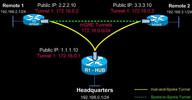
Our DMVPN Network
The diagram below depicts our DMVPN example network. Our goal is to connect the two remote networks (Remote 1 & 2) with the company headquarters. The headquarters router R1 is the central Hub router that will hold the NHRP database containing all spoke routers, their public IP addresses and LAN networks.
 Four Steps to Fully Configure Cisco DMVPN
To help simplify the configuration of DMVPN we’ve split the process into 4 easy-to-follow steps. Each step is required to be completed before moving to the next one. These steps are:
Configuring the DMVPN Hub – R1 Router
Configuring the Hub router (R1) is simple. After configuring the router’s LAN and WAN interfaces we create our mGRE tunnel interface. Let's start with the router’s Ethernet interfaces:
interface FastEthernet0/0
description LAN-Network
ip address 192.168.1.1 255.255.255.0
duplex auto
speed auto
!
interface FastEthernet0/1
description WAN-Network
ip address 1.1.1.10 255.255.255.0
duplex auto
speed auto
Next, we configure the Tunnel0 interface. Notice this is an almost typical tunnel interface configuration with some minor but important changes that have been highlighted:
interface Tunnel0
description mGRE - DMVPN Tunnel
ip address 172.16.0.1 255.255.255.0
no ip redirects
ip nhrp authentication firewall
ip nhrp map multicast dynamic
ip nhrp network-id 1
tunnel source 1.1.1.10
tunnel mode gre multipoint
Engineers familiar with GRE Tunnels will immediately notice the absence of the tunnel destination command. It has been replaced with the tunnel mode gre multipointcommand, which designates this tunnel as a multipoint GRE tunnel.
The ip nhrp map multicast dynamic command enables the forwarding of multicast traffic across the tunnel to dynamic spokes. This is usually required by routing protocols such as OSPF and EIGRP. In most cases, DMVPN is accompanied by a routing protocol to send and receive dynamic updates about the private networks.
The ip nhrp network-id 1 command is used to identify this DMVPN cloud. All routers participating in this DMVPN cloud must have the same network-id configured in order for tunnels to form between them.
The ip nhrp authentication command is used to allow the authenticated updates and queries to the NHRP Database, ensuring unwanted queries are not provided with any information about the DMVPN network.
Configuring the DMVPN Spokes – R2 & R3 Routers
Spoke router configuration is similar to that of the hub. First configure the LAN and WAN interfaces:
interface FastEthernet0/0
description LAN-Network
ip address 192.168.2.1 255.255.255.0
duplex auto
speed auto
!
interface FastEthernet0/1
description WAN-Network
ip address 2.2.2.10 255.255.255.0
duplex auto
speed auto
Next, it’s time to build that tunnel:
interface Tunnel0
description R2 mGRE - DMVPN Tunnel
ip address 172.16.0.2 255.255.255.0
no ip redirects
ip nhrp authentication firewall
ip nhrp map multicast dynamic
ip nhrp map 172.16.0.1 1.1.1.10
ip nhrp map multicast 1.1.1.10
ip nhrp network-id 1
ip nhrp nhs 172.16.0.1
tunnel source FastEthernet0/1
tunnel mode gre multipoint
After a couple of seconds, we receive confirmation that our tunnel interface is up:
*Sep 9 21:27:29.774: %LINEPROTO-5-UPDOWN: Line protocol on Interface Tunnel0, changed state to up
The ip nhrp nhs 172.16.0.1 command tells our spoke router who the Next Hop Server (NHS) is, while the ip nhrp map 172.16.0.1 1.1.1.10 command maps the NHS address (172.16.0.1) to the Hub’s (R1) public IP address (1.1.1.10).
The ip nhrp map multicast 1.1.1.10 ensures multicast traffic is sent only from spokes to the hub and not from spoke to spoke. All multicast traffic should be received by the hub, processed and then updates are sent out to the spokes.
Lastly, notice that tunnel source FastEthernet0/1 command. All spokes with dynamic WAN IP address must be configured to bind the physical WAN interface as the tunnel source. This way, when the spoke’s WAN IP changes, it will be able to update the NHS server with its new WAN IP address.
Note: In R2’s configuration, we’ve configured a static IP address on its WAN interface FastEthernet0/1, but for the sake of this example, let us assume it was dynamically provided by the ISP.
R3’s configuration follows, similar to that of the R2 spoke router:
interface FastEthernet0/0
description LAN-Network
ip address 192.168.3.1 255.255.255.0
duplex auto
speed auto
!
interface FastEthernet0/1
description WAN-Network
ip address 3.3.3.10 255.255.255.0
duplex auto
speed auto
Next, our tunnel configuration:
interface Tunnel0
description R3 mGRE - DMVPN Tunnel
ip address 172.16.0.3 255.255.255.0
no ip redirects
ip nhrp authentication firewall
ip nhrp map multicast dynamic
ip nhrp map 172.16.0.1 1.1.1.10
ip nhrp map multicast 1.1.1.10
ip nhrp network-id 1
ip nhrp nhs 172.16.0.1
tunnel source FastEthernet0/1
tunnel mode gre multipoint
Note: In R3’s configuration, we’ve configured a static IP address on its WAN interface FastEthernet0/1, but for the sake of this example, let us assume it was dynamically provided by the ISP.
This completes the DMVPN configuration on our central hub and two spoke routers. It is now time to verify the DMVPNs are working correctly.
Verifying DMVPN Functionality at the R1 HUB Router
After completing our routers configuration, it’s time to verify everything is working as planned.
First we turn to our main hub, R1, and check the DMVPN by using the show dmvpn command:
R1# show dmvpn
Legend: Attrb --> S - Static, D - Dynamic, I - Incomplete
N - NATed, L - Local, X - No Socket
# Ent --> Number of NHRP entries with same NBMA peer
NHS Status: E --> Expecting Replies, R --> Responding
UpDn Time --> Up or Down Time for a Tunnel
==========================================================================
Interface: Tunnel0, IPv4 NHRP Details
Type:Hub, NHRP Peers:2,
# Ent Peer NBMA Addr Peer Tunnel Add State UpDn Tm Attrb
----- ---------------------- --------------- ----- -------- -----
1 2.2.2.10 172.16.0.2 UP 00:04:58 D
1 3.3.3.10 172.16.0.3 UP 00:04:12 D
The output of our command provides us with some valuable information. To start with, the router provides an explanation for each column presented (right under the show command) but we are still going to cover them so that we are not left with any unanswered questions.
The first column #Ent shows the number of entries that exist in the NHRP Database for the same spoke. Usually, we wouldn’t expect to see more than one for each spoke.
The second column Peer NBMA Addr presents the spoke’s public IP address, while the third column, Peer Tunnel Add, shows each spoke’s local Tunnel’s IP address.
Next, the State column shows the current state the tunnel is in. In our case, both tunnels are UP. Right next to the State is the UpDN Tm, which is the Up or Down Time of the current State. This is a very important bit of information as you can clearly see out how long your tunnel has been in its current state.
For our example, both spokes have been up for almost 5 minutes.
Lastly, the Attrib column shows the type of tunnels established by the spokes. D stands for Dynamic, S for Static and I for Incomplete. Usually dynamic spokes will create D type tunnels. Tunnels established from the spokes to the Hub router are expected to be S type, since the Hub remains static.
Verifying DMVPN Functionality at the R2 & R3 Spoke Router
Turning to R2 router, our first spoke, we can repeat the same show dmvpn command and obtain a list of dmvpns currently created:
R2# show dmvpn
Legend: Attrb --> S - Static, D - Dynamic, I - Incomplete
N - NATed, L - Local, X - No Socket
# Ent --> Number of NHRP entries with same NBMA peer
NHS Status: E --> Expecting Replies, R --> Responding
UpDn Time --> Up or Down Time for a Tunnel
==========================================================================
Interface: Tunnel0, IPv4 NHRP Details
Type:Spoke, NHRP Peers:1,
# Ent Peer NBMA Addr Peer Tunnel Add State UpDn Tm Attrb
----- ---------------------- --------------- ----- -------- -----
1 1.1.1.10 172.16.0.1 UP 00:06:35 S
As expected, R2’s output shows one entry only. When traffic needs to be directed to R3, a second GRE tunnel will come up. We’ll try this soon. For now let’s check our third remote site, R3 spoke router
Using the same show dmvpn command we obtain the following similar output:
R3# show dmvpn
Legend: Attrb --> S - Static, D - Dynamic, I - Incomplete
N - NATed, L - Local, X - No Socket
# Ent --> Number of NHRP entries with same NBMA peer
NHS Status: E --> Expecting Replies, R --> Responding
UpDn Time --> Up or Down Time for a Tunnel
==========================================================================
Interface: Tunnel0, IPv4 NHRP Details
Type:Spoke, NHRP Peers:1,
# Ent Peer NBMA Addr Peer Tunnel Add State UpDn Tm Attrb
----- ---------------------- --------------- ----- -------- -----
1 1.1.1.10 172.16.0.1 UP 00:06:55 S
Protecting - Encrypting DMVPN mGRE Tunnels with IPSec
Since we have our GRE tunnels up and running, we need to encrypt them using IPSec to ensure data confidentiality. Protecting GRE Tunnels is covered in great depth in our Protected GRE over IPSec article, so we are going to simply display the commands here without repeating the topic.
First stop is our headquarters R1 Hub router:
crypto isakmp policy 1
encr 3des
hash md5
authentication pre-share
group 2
lifetime 86400
!
crypto isakmp key firewall.cx address 0.0.0.0
!
crypto ipsec transform-set TS esp-3des esp-md5-hmac
!
crypto ipsec profile protect-gre
set security-association lifetime seconds 86400
set transform-set TS
!
interface Tunnel 0
tunnel protection ipsec profile protect-gre
Notice the command crypto isakmp key firewall.cx address 0.0.0.0 0.0.0.0. The peer address for which the isakmp key is valid is0.0.0.0 0.0.0.0, which means every possible host on the Internet. When our remote routers (spokes) have dynamic IP addresses,0.0.0.0 0.0.0.0 must be used.
The following configuration applies to R2 & R3 spoke routers:
crypto isakmp policy 1
encr 3des
hash md5
authentication pre-share
group 2
lifetime 86400
!
crypto isakmp key firewall.cx address 0.0.0.0 0.0.0.0
!
crypto ipsec transform-set TS esp-3des esp-md5-hmac
!
crypto ipsec profile protect-gre
set security-association lifetime seconds 86400
set transform-set TS
!
interface Tunnel 0
tunnel protection ipsec profile protect-gre
Again we’ve defined 0.0.0.0 0.0.0.0 as the isakmp peer address. While the hub’s public IP address is known we must keep in mind that R2 and R3 can build dynamic VPN tunnel between them. Taking into consideration that their public IP address is dynamic it is imperative to use 0.0.0.0 0.0.0.0 for the remote peer.
Verifying the DMVPN Crypto Tunnels
Once all routers are configured IPSec VPN tunnels are brought up. We can verify this by using the show crypto session command at our R1 hub router:
R1# show crypto session
Crypto session current status
Interface: Tunnel0
Session status: UP-ACTIVE
Peer: 2.2.2.10 port 500
IKE SA: local 1.1.1.10/500 remote 2.2.2.10/500 Active
IPSEC FLOW: permit 47 host 1.1.1.10 host 2.2.2.10
Active SAs: 2, origin: crypto map
Interface: Tunnel0
Session status: UP-ACTIVE
Peer: 3.3.3.10 port 500
IKE SA: local 1.1.1.10/500 remote 3.3.3.10/500 Active
IPSEC FLOW: permit 47 host 1.1.1.10 host 3.3.3.10
Active SAs: 2, origin: crypto map
Routing Between DMVPN mGRE Tunnels
Last step involves enabling routing in our DMVPN network. This is required so that the hub and spoke routers are aware which packets need to be sent via the VPN network.
There are two ways this can be achieved: 1) Static routes 2) Routing protocol.
For the sake of simplicity we are going to focus on static routes. DMVPN and routing protocol configuration will be covered in another article.
Configuring the necessary static routes is very simple. All that is required is a set of simply static routes on each router (hub and spoke), pointing to the other networks.
On the R1 hub router:
ip route 192.168.2.0 255.255.255.0 172.16.0.2
ip route 192.168.3.0 255.255.255.0 172.16.0.3
On R2 spoke router:
ip route 192.168.1.0 255.255.255.0 172.16.0.1
ip route 192.168.3.0 255.255.255.0 172.16.0.3
And finally on R3 spoke router:
ip route 192.168.1.0 255.255.255.0 172.16.0.1
ip route 192.168.2.0 255.255.255.0 172.16.0.2
Our DMVPN Network is Ready!
At this point, our DMVPN network is ready and fully functional. All networks are connected between each other and dynamic VPN tunnels between spokes can be established. GRE tunnels are protected properly, providing data confidentiality and ip routing is enabled.
As a final step, we can try sending traffic between the spokes and verify the dynamic tunnel is being established:
From R2 spoke router, we try to ping R3’s LAN IP address:
R2# ping 192.168.3.1
Type escape sequence to abort.
Sending 5, 100-byte ICMP Echos to 192.168.3.1, timeout is 2 seconds:
.!!!!
Success rate is 80 percent (4/5), round-trip min/avg/max = 1/1/4 ms
It is evident that the two spoke routers have established communication.
The DMVPN is up and routing is working perfectly:
R2# show dmvpn
Legend: Attrb --> S - Static, D - Dynamic, I - Incomplete
N - NATed, L - Local, X - No Socket
# Ent --> Number of NHRP entries with same NBMA peer
NHS Status: E --> Expecting Replies, R --> Responding
UpDn Time --> Up or Down Time for a Tunnel
==========================================================================
Interface: Tunnel0, IPv4 NHRP Details
Type:Spoke, NHRP Peers:2,
# Ent Peer NBMA Addr Peer Tunnel Add State UpDn Tm Attrb
----- ---------------------- --------------- ----- -------- -----
1 1.1.1.10 172.16.0.1 UP 00:39:05 S
1 3.3.3.10 172.16.0.3 UP 00:00:08 D
This concludes our DMVPN configuration article.
|
Cisco GRE and IPSec - GRE over IPSec - Selecting and Configuring GRE IPSec Tunnel or Transport Mode
GRE Tunnels are very common amongst VPN implementations thanks to their simplicity and ease of configuration. With broadcasting and multicasting support, as opposed to pure IPSec VPNs, they tend to be the number one engineers' choice, especially when routing protocols are used amongst sites.
The problem with GRE is that it is an encapsulation protocol, which means that while it does a terrific job providing connectivity between sites, it does a terrible job encrypting the data being transferred between them. GRE is stateless, offering no flow control mechanisms (think of UDP). This is where the IPSec protocol comes into the picture.
IPSec’s objective is to provide security services for IP packets such as encrypting sensitive data, authentication, protection against replay and data confidentiality. IPSec is extensively covered in our IPSec protocol article.
IPSec can be used in conjunction with GRE to provide top-notch security encryption for our data, thereby providing a complete secure and flexible VPN solution. IPSec can operate in two different modes, Tunnel mode and Transport mode. Both of these modes are covered extensively in our Understanding VPN IPSec Tunnel Mode and IPSec Transport Mode article. Additionally, Cisco GRE Tunnel configuration is covered in our Configuring Cisco Point-to-Point GRE Tunnels. We highly recommend reading these articles before proceeding as it is a prerequisite for understanding the information covered here.
As with IPSec, when configuring GRE with IPSec there are two modes in which GRE IPSec can be configured, GRE IPSec Tunnel mode and GRE IPSec Transport mode.
This article examines the difference between GRE IPSec Tunnel and GRE IPSec Transport mode, and explains the packet structure differences along with the advantages and disadvantages of each mode.
GRE IPSec Tunnel Mode
With GRE IPSec tunnel mode, the whole GRE packet (which includes the original IP header packet), is encapsulated, encrypted and protected inside an IPSec packet. GRE over IPSec Tunnel mode provides additional security because no part of the GRE tunnel is exposed, however, there is a significant overhead added to the packet. This additional overhead decreases the usable free space for our payload (Original IP packet), that means possibly more fragmentation will occur when transmitting data over a GRE IPSec Tunnel VPN.
IPSec Tunnel mode is the default configuration option for both GRE and non-GRE IPSec VPNs. When configuring the IPSec transform set, no other configuration commands are required to enable tunnel mode:
R1(config)# crypto ipsec transform-set TS esp-3des esp-md5-hmac
Calculating GRE IPSec Tunnel Mode Overhead
Calculating the overhead will help us understand how much additional space GRE over IPSec in Tunnel mode requires and our effective usable space.
The packet structure below shows an example of a GRE over IPSec in Tunnel mode: 
Two important points to keep in mind when calculating the overhead:
- Depending on the encryption algorithm used in the crypto transform set, the Initialization Vector (IV) shown could be 8 or 16 bytes long. For example DES or 3DES introduces an 8-byte IV field, where as AES introduces a 16-byte IV field. In our example, we are using 3DES encryption, therefore producing a 8-byte IV field.
- The ESP Trailer will usually vary in size. Its job is to ensure that the Pad Length, Next Header fields (both 1-byte long and contained within the ESP Trailer) & ESP Auth.Trailer are aligned on a 4-byte boundary. This means the total number of bytes, when adding the three fields together, must be a multiple of 4.
Following is the calculated overhead:
ESP Overhead: 20 (IP Hdr) + 8 (ESP Hdr) + 8 (IV) + 4 (ESP Trailer) + 12 (ESP Auth) = 52 Bytes
Note: ESP Trailer has been calculated as 4 bytes as per above note.
GRE Overhead: 20 (GRE IP Hdr) + 4 (GRE) = 24 Bytes
Total Overhead: 52 + 24 = 76 Bytes
GRE IPSec Transport Mode
With GRE IPSec transport mode, the GRE packet is encapsulated and encrypted inside the IPSec packet, however, the GRE IP Header is placed at the front. This effectively exposes the GRE IP Header as it is not encrypted the same way it is in Tunnel mode.
IPSec Transport mode is not used by default configuration and must be configured using the following command under the IPSec transform set:
R1(config)# crypto ipsec transform-set TS esp-3des esp-md5-hmac
R1(cfg-crypto-trans)# mode transport
GRE IPSec transport mode does have a few implementation restrictions. It is not possible to use GRE IPSec transport mode if the crypto tunnel transits a device using Network Address Translation (NAT) or Port Address Translation (PAT). In such cases, Tunnel mode must be used.
Finally, if the GRE tunnel endpoints and Crypto tunnel endpoints are different, GRE IPSec transport mode cannot be used.
These limitations seriously restrict the use and implementation of the transport mode in a WAN network environment.
Calculating GRE IPSec Transport Mode Overhead
Calculating the overhead will help us understand how much space GRE over IPSec in Transport mode uses and our effective usable space.
The packet structure below shows an example of GRE over IPSec in transport mode:
Again, two important points that must kept in mind when calculating the overhead:
- Depending on the encryption algorithm used in the crypto transform set, the Initialization Vector (IV) shown could be 8 or 16 bytes long. For example DES or 3DES introduces an 8-byte IV field, where as AES introduces a 16-byte IV field. In our example, we are using 3DES encryption, therefore producing a 8-byte IV field.
- The ESP Trailer will usually vary in size. Its job is to ensure that the Pad Length, Next Header fields (both 1-byte long and contained within the ESP Trailer) & ESP Auth.Trailer are aligned on a 4-byte boundary. This means the total number of bytes, when adding the three fields together, must be a multiple of 4.
Following is the calculated overhead:
ESP Overhead: 20 (IP Hrd) + 8 (ESP Hdr) + 8 (IV) + 4 (ESP Trailer) + 12 (ESP Auth) = 52 Bytes
Note: ESP Trailer has been calculated as 4 bytes as per above note.
GRE Overhead: 4 (GRE) = 4 Bytes
Total Overhead: 52 + 4 = 56 Bytes
It is evident that GRE IPSec Transport mode saves approximately 20 bytes per packet overhead. This might save a moderate amount of bandwidth on a WAN link, however, there is no significant increase in CPU performance by using this mode.
Conclusion
When comparing GRE over IPSec tunnel and GRE over IPSec transport mode, there are significant differences that cannot be ignored.
If the GRE tunnels and crypto endpoints are not the same (IP address wise), transport mode in definitely not an option.
If packets traverse a device (router) where NAT or PAT is used then again, transport mode cannot be used.
On the other hand, tunnel mode seems to pay-off its 20-byte additional overhead by being flexible enough to be used in any type of WAN environment and offering increased protection by encrypting the GRE IP Header inside the ESP packet.
Taking in consideration the small additional CPU load the tunnel mode produces and advantages it offers, we don’t believe it’s a coincidence Cisco has selected this mode in IPSec’s default configuration.
Configuring Cisco SSL VPN AnyConnect (WebVPN) on Cisco IOS Routers
|
Web SSL VPN delivers the following three modes of SSL VPN access:
• Clientless - Clientless mode provides secure access to private web resources and will provide access to web content. This mode is useful for accessing most content that you would expect to access in a web browser such as Internet access, web-based intranet, webmail etc.
• Thin Client (port-forwarding Java applet) - Thin client mode extends the capability of the cryptographic functions of the web browser to enable remote access to TCP-based applications such as Post Office Protocol version 3 (POP3), Simple Mail Transfer Protocol (SMTP), Internet Message Access protocol (IMAP), Telnet and Secure Shell (SSH).
• Tunnel Mode (AnyConnect Secure Mobility Client) - Full tunnel client mode offers extensive application support through its dynamically downloaded Cisco AnyConnect VPN Client (next-generation SSL VPN Client) for SSL VPN. Full tunnel client mode delivers a lightweight, centrally configured and easy-to-support SSL VPN tunneling client that provides network layer access to virtually any application.
The advantage of SSL VPN comes from its accessibility from almost any Internet-connected system without needing to install additional desktop software.
Introducing Cisco SSL AnyConnect VPN - WebVPN
Cisco SSL AnyConnect VPN is a real trend these days – it allows remote users to access enterprise networks from anywhere on the Internet through an SSL VPN gateway using a web browser. During the establishment of the SSL VPN with the gateway, the client downloads and installs the AnyConnect VPN client from VPN gateway. This feature allows easy access to services within the company’s network and simplifies the VPN configuration on the SSL VPN gateway, reducing dramatically the administrative overhead for system administrators.
The Cisco secure WebVPN router login screen
The Cisco SSL AnyConnect VPN client was introduced in Cisco IOS 12.4(15)T and has been in development since then. Today, Cisco SSL AnyConnect VPN client supports all Windows platforms, Linux Redhat, Fedora, CentOS, iPhones, iPads and Android mobile phones.
Regardless of the client (PC, smartphone etc), the router configuration remains the same, while the appropriate VPN client software is downloaded by the client connecting to the VPN gateway (router).
Smartphones such as iPhones (iPAD included) and Android can download the Cisco VPN AnyConnect Secure Mobility Client directly from iTunes (Apple) or the Google Play store respectively (android phones). To download it, connect to your store and search for ‘Cisco AnyConnect’.
This article will use a Windows 7 workstation and Samsung Galaxy SII running Ice Cream Sandwich (4.0.4), as mobile clients.
To download VPN AnyConnect Secure Mobility Client packages files for Windows, MacOS X and Linux platforms, free, simply visit ourCisco Download section. The latest version of the client was made available at the time of writing this article.
Once our client is downloaded and installed on our Windows 7 workstation it will be ready to initiate the VPN connection to our VPN Gateway: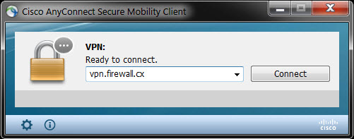
Steps to Configure and Enable SSL AnyConnect VPN Secure Mobility Client
- Upload AnyConnect Secure Mobility Client to our Cisco Router
- Generate RSA Keys
- Declare the Trustpoint & Create Self-Signed Certificate
- Configure WebVPN Pool IP addresses assigned to the VPN Users
- Enable and Configure AAA Authentication for SSL VPN & Create User Accounts
- Enable WebVPN License
- Configure and enable WebVPN Gateway
- Configure and enable SSL VPN Context
- Configure default group policy, authentication list and final parameters for WebVPN
Note: The complete working configuration for WebSSL VPN AnyConnect can be found at the end of this article.
Uploading AnyConnect Secure Mobility Client Package to Our Cisco Router
The first step is to upload the Cisco AnyConnect client to the router’s flash memory. Depending on the type of clients you might need to upload more than one VPN AnyConnect client package. For our article, we will be using the latest VPN AnyConnect client for Windows, which at the time of writing was version 3.1.00495 (anyconnect-win-3.1.00495-k9.pkg). This client is available for download in our Cisco Download Section.
R1# copy tftp flash:
Address or name of remote host []? 192.168.9.74
Source filename []? anyconnect-win-3.1.00495-k9.pkg
Destination filename [anyconnect-win-3.1.00495-k9.pkg]?
Accessing tftp://192.168.9.74/anyconnect-win-3.1.00495-k9.pkg...
Loading anyconnect-win-3.1.00495-k9.pkg from 192.168.9.74 (via Virtual-Access3): !!!!!!!!!!!!!!!!!!!!!
[OK - 29806775 bytes]
29806775 bytes copied in 325.852 secs (90 kbytes/sec)
Generate RSA Keys
The next step is to generate our RSA 1024bit keys. The crypto key generate rsa command depends on the hostname and ip domain-name commands. This crypto command generates a Rivest, Shamir, Adleman (RSA) key pair, which includes one public RSA key and one private RSA key, with a key modulus size of 1024 (usually):
R1(config)# crypto key generate rsa label my-rsa-keys modulus 1024
The name for the keys will be: my-rsa-keys
% The key modulus size is 1024 bits
% Generating 1024 bit RSA keys, keys will be non-exportable...
[OK] (elapsed time was 1 seconds)
Note: The crypto key generate rsa command will not appear in the router’s running or startup configuration
Declare the Trustpoint & Create Self-Signed Certificate
Once complete, we need to declare the trustpoint that the router should use by using the command crypto pki trustpoint command in global configuration mode. When declaring a trustpoint, we can specify certain characteristics in its subcommands as shown in our configuration:
crypto pki trustpoint my-trustpoint
enrollment selfsigned
subject-name CN=firewallcx-certificate
rsakeypair my-rsa-keys
!
crypto pki enroll my-trustpoint
% Include the router serial number in the subject name? [yes/no]: yes
% Include an IP address in the subject name? [no]: no
Generate Self Signed Router Certificate? [yes/no]: yes
Router Self Signed Certificate successfully created
Configure WebVPN Pool IP Addresses
WebVPN users will need to be assigned a LAN IP address so they can communicate with our network. The following command specifies the pool of ip addresses that will be assigned to our users. This can be either part of our LAN network or a completely different network. Since we have plenty of spare IP addresses, we’ll be using a small portion of them:
ip local pool webvpn-pool 192.168.9.80 192.168.9.85
Note we have named this pool webvpn-pool.
Enable and Configure AAA Authentication for SSL VPN - Create User VPN Accounts
AAA stands for Authentication, Authorization and Accounting. We need to enable AAA in order to use it for our user authentication.
aaa new-model
aaa authentication login sslvpn local
username chris secret firewall.cx
It could be that AAA is already enabled on the router, in which case we only need to define an authentication list (we named it ‘sslvpn’) to use the router’s local user database for user authentication.
Enable WebVPN License
When the WebVPN service is enabled for the first time on an ISR Generation 2 Cisco router (1900, 2900 & 3900 series), with the 15.x version IOS software or newer, the router will prompt us to accept the End-User License Agreement (EULA) before enabling and activating the service.
It is imperative to accept the EULA in order to proceed:
R1(config)# webvpn gateway Cisco-WebVPN-Gateway
PLEASE READ THE FOLLOWING TERMS CAREFULLY. INSTALLING THE LICENSE OR
LICENSE KEY PROVIDED FOR ANY CISCO PRODUCT FEATURE OR USING SUCH
PRODUCT FEATURE CONSTITUTES YOUR FULL ACCEPTANCE OF THE FOLLOWING
TERMS. YOU MUST NOT PROCEED FURTHER IF YOU ARE NOT WILLING TO BE BOUND
BY ALL THE TERMS SET FORTH HEREIN.
……. Output omitted
Activation of the software command line interface will be evidence of
your acceptance of this agreement.
ACCEPT? [yes/no]: yes
After accepting the EULA, we can verify the WebSSL VPN service is activated by issuing the show license all command. Usually StoreIndex 4 contains the WebSSL VPN reference:
R1# show license all
License Store: Primary License Storage
StoreIndex: 0 Feature: ipbasek9 Version: 1.0
License Type: Permanent
License State: Active, In Use
License Count: Non-Counted
License Priority: Medium
StoreIndex: 1 Feature: securityk9 Version: 1.0
License Type: Permanent
License State: Active, In Use
License Count: Non-Counted
License Priority: Medium
License Store: Built-In License Storage
StoreIndex: 0 Feature: securityk9 Version: 1.0
License Type: EvalRightToUse
License State: Inactive
Evaluation total period: 8 weeks 4 days
Evaluation period left: 8 weeks 4 days
Period used: 0 minute 0 second
License Count: Non-Counted
License Priority: None
StoreIndex: 4 Feature: SSL_VPN Version: 1.0
License Type: EvalRightToUse
License State: Active, In Use
Evaluation total period: 8 weeks 4 days
Evaluation period left: 8 weeks 3 days
Period used: 0 minute 1 second
Transition date: Nov 18 2012 22:14:16
License Count: 100/0 (In-use/Violation)
License Priority: Low
Notice the License Type mention: EvalRightToUse. This means that this is an evaluation license, a license to evaluate. At the end of the8 ½ week evaluation period, the ISRG2 Cisco router license will not terminate the Web SSL_VPNlicense, and it will continue to work.
Configure and Enable WebVPN Gateway
After taking care of the licensing it’s time to begin working on the WebVPN Virtual Gateway configuration. The WebVPN Virtual Gateway enables the interface or IP address and port number to which the WebVPN service will ‘listen’ for incoming connections and also determines the encryption that will be used.
webvpn gateway Cisco-WebVPN-Gateway
ip address 74.200.90.5 port 443
ssl encryption rc4-md5
ssl trustpoint my-trustpoint
inservice
Note: If the interface the WebVPN will be running on has a dynamic IP address, for example Dialer0 (ATM ADSL Interface), the ip address 74.200.90.5 port 443 command can be replaced with ip interface Dialer0 port 443, where ‘Dialer0’ is the dynamic interface.
Note: There is a big bug that causes Windows clients browser to report errors such as ""The page isn't redirecting properly"" when trying to connect to the SSL WebVPN Gateway. According to Cisco, this bug surfaces as a Windows machine gets updated with security update KB2585542. Cisco's workaround solution is to use the rc4-md5 encryption instead, as shown above.
For those interested in reading up on this bug, Cisco has assigned bug ID: CSCtx38806 with the description "IOS SSL VPN fails to connect after microsoft security update KB258554".
Configure and Enable SSL VPN Context
The SSL VPN context is used to configure a number of parameters for our Web VPN server, these include:
- Gateway and domain associated
- AAA user authentication method
- Group policy associated
- The remote user portal (web page)
- Limit number of WebVPN SSL user sessions
Most of these parameters are configured in our group policy. This group policy is then set as the default-group policy for our Web SSL VPN.
webvpn context Cisco-WebVPN
title "Firewall.cx WebVPN - Powered By Cisco"
!
acl "ssl-acl"
permit ip 192.168.9.0 255.255.255.0 192.168.9.0 255.255.255.0
login-message "Cisco Secure WebVPN"
!
policy group webvpnpolicy
functions svc-required
functions svc-enabled
filter tunnel ssl-acl
svc address-pool "webvpn-pool" netmask 255.255.255.0
svc rekey method new-tunnel
svc split include 192.168.9.0 255.255.255.0
Let’s explain what all the above commands do:
The webvpn context command is used to create a context named which we have named Cisco-WebVPN. The title command sets the text that will be displayed at the web browser’s Page Title and at the top of the login screen.
The acl “ssl-acl” command configures the access lists for this context. It basically governs what the web vpn users will have access to. We’ve provided our webVPN users full access to the 192.168.9.0 network.
Our webvpn users' IP addresses have already been defined in the webvpn-pool (192.168.9.80 to 192.168.0.85). Instead of typing each IP address within that range into our ACL list we simply configure the router to allow the 192.168.9.0 network as a source and destination in our VPN tunnel. This ensures any IP in the 192.168.9.0 range assigned to our vpn clients will have access to our LAN (192.168.9.0)
The login-message command defines the text that will be shown in the login section of the webvpn webpage. These messages are also visible in our WebVPN login screen at the beginning of our article.
Since our webvpn pool is part of the same network we just set the 192.168.9.0 network as the source and destination IP address.
Next, we define a group policy. The group policy configures a number of important parameters. We named our group policywebvpnpolicy.
The functions svc-enabled & svc-required commands ensure tunnel-mode is enabled and required. The combination of these two commands will force the VPN user’s PC to start downloading the AnyConnect software client as soon as he authenticates successfully. This is called tunnel-mode operation.
Alternatively, without the svc-required command, a webpage will be presented from which the user can directly launch any configured web service in our webvpn portal or selectively initiate tunnel-mode and start downloading the AnyConnect software client.
Note: The acronym SVC stands for SSL VPN Client
The screenshot below shows the AnyConnect Secure Mobility Client installation process. Keep in mind that these screenshots applyafter the complete configuration of our router's SSL WebVPN service:
During the installation, the user will receive a number of prompts & security warnings about the publisher and website’s certificate verification. Administrators and engineers should instruct their VPN users to accept/allow the installation of the certificates and software client when prompted.
Shortly after the acceptance of certificates and confirming to the web browser to allow the installation of the client, the AnyConnect Secure Mobility Client Downloader will begin:
The filter tunnel ssl-acl command instructs the webvpn gateway to use ssl-acl access list to define the access vpn users will have.
The svc address-pool command defines the pool that will be used to assign IP addresses to our vpn users.
The svc rekey method new-tunnel specifies that the SVC establishes a new tunnel during SVC rekey.
The svc split command enables split tunneling, instructing which network traffic will be sent through the vpn tunnel. If this command is not included, vpn users will not be allowed to access the Internet while connected to the vpn.
Configure Default Group Policy, Authentication List and Final Parameters
Now we will configure the policy we just created as the default policy, set the aaa authentication list (sslvpn) to be used for user authentication and maximum users for the service. Lastly, we enable our webvpn context:
default-group-policy webvpnpolicy
aaa authentication list sslvpn
gateway Cisco-WebVPN-Gateway
max-users 2
!
ssl authenticate verify all
!
url-list "rewrite"
inservice
The ssl authenticate verify all command enables SSL configurations for backend server connections. While we are not using any such backend services, it’s a good option to always have enabled.
Supporting Multiple Group Policies on AnyConnect
Administrators and engineers who have worked with the classic Cisco IPSec VPN client will wonder how they can support multiple groups with different access rights using AnyConnect. The fact is that AnyConnect does support multiple groups, however it requires a radius server at the backend.
AnyConnect on a Cisco router without a radius server will only allow support for one group policy.
Complete WebVPN SSL AnyConnect Configuration
Finally, below is the complete Web VPN SSL AnyConnect configuration of our router:
aaa new-model
aaa authentication login sslvpn local
!
username chris secret firewall.cx
!
crypto key generate rsa label my-rsa-keys modulus 1024
!
crypto vpn anyconnect flash0:/webvpn/anyconnect-win-3.1.00495-k9.pkg sequence 1
!
ip local pool webvpn-pool 192.168.9.80 192.168.9.85
!
webvpn gateway Cisco-WebVPN-Gateway
ip address 74.200.90.5 port 443
ssl encryption rc4-md5
ssl trustpoint my-trustpoint
inservice
!
webvpn context Cisco-WebVPN
title "Firewall.cx WebVPN Gateway"
!
acl "ssl-acl"
permit ip 192.168.9.0 255.255.255.0 192.168.9.0 255.255.255.0
login-message "Cisco Secure WebVPN"
!
policy group webvpnpolicy
functions svc-required
functions svc-enabled
filter tunnel ssl-acl
svc address-pool "webvpn-pool" netmask 255.255.255.0
svc rekey method new-tunnel
svc split include 192.168.9.0 255.255.255.0
default-group-policy webvpnpolicy
aaa authentication list sslvpn
gateway Cisco-WebVPN-Gateway
max-users 2
!
ssl authenticate verify all
!
url-list "rewrite"
inservice
This concludes our Cisco SSL VPN AnyConnect configuration for Cisco IOS Routers.
Configuring Site to Site IPSec VPN Tunnel Between Cisco Routers
Site-to-Site IPSec VPN Tunnels are used to allow the secure transmission of data, voice and video between two sites (e.g offices or branches). The VPN tunnel is created over the Internet public network and encrypted using a number of advanced encryption algorithms to provide confidentiality of the data transmitted between the two sites.
This article will show how to setup and configure two Cisco routers to create a permanent secure site-to-site VPN tunnel over the Internet, using the IP Security (IPSec) protocol. In this article we assume both Cisco routers have a static public IP address. Readers interested in configuring support for dynamic public IP address endpoint routers can refer to our Configuring Site to Site IPSec VPN with Dynamic IP Endpoint Cisco Routers article.
IPSec VPN tunnels can also be configured using GRE (Generic Routing Encapsulation) Tunnels with IPsec. GRE tunnels greatly simply the configuration and administration of VPN tunnels and are covered in our Configuring Point-to-Point GRE VPN Tunnels article. Lastly, DMVPNs – a new VPN trend that provide major flexibility and almost no administration overhead can also be examined by reading ourUnderstanding Cisco Dynamic Multipoint VPN (DMVPN), Dynamic Multipoint VPN (DMVPN) Deployment Models & Architectures andConfiguring Cisco Dynamic Multipoint VPN (DMVPN) - Hub, Spokes , mGRE Protection and Routing - DMVPN Configuration articles.
ISAKMP (Internet Security Association and Key Management Protocol) and IPSec are essential to building and encrypting the VPN tunnel. ISAKMP, also called IKE (Internet Key Exchange), is the negotiation protocol that allows two hosts to agree on how to build an IPsec security association. ISAKMP negotiation consists of two phases: Phase 1 and Phase 2.
Phase 1 creates the first tunnel, which protects later ISAKMP negotiation messages. Phase 2 creates the tunnel that protects data. IPSec then comes into play to encrypt the data using encryption algorithms and provides authentication, encryption and anti-replay services.
IPSec VPN Requirements
To help make this an easy-to-follow exercise, we have split it into two steps that are required to get the Site-to-Site IPSec VPN Tunnel to work.
These steps are:
(1) Configure ISAKMP (ISAKMP Phase 1)
(2) Configure IPSec (ISAKMP Phase 2, ACLs, Crypto MAP)
Our example setup is between two branches of a small company, these are Site 1 and Site 2. Both the branch routers connect to the Internet and have a static IP Address assigned by their ISP as shown on the diagram:

Site 1 is configured with an internal network of 10.10.10.0/24, while Site 2 is configured with network 20.20.20.0/24. The goal is to securely connect both LAN networks and allow full communication between them, without any restrictions.
Configure ISAKMP (IKE) - (ISAKMP Phase 1)
IKE exists only to establish SAs (Security Association) for IPsec. Before it can do this, IKE must negotiate an SA (an ISAKMP SA) relationship with the peer.
To begin, we’ll start working on the Site 1 router (R1).
First step is to configure an ISAKMP Phase 1 policy:
R1(config)# crypto isakmp policy 1
R1(config-isakmp)# encr 3des
R1(config-isakmp)# hash md5
R1(config-isakmp)# authentication pre-share
R1(config-isakmp)# group 2
R1(config-isakmp)# lifetime 86400
The above commands define the following (in listed order):
3DES - The encryption method to be used for Phase 1.
MD5 - The hashing algorithm
Pre-share - Use Pre-shared key as the authentication method
Group 2 - Diffie-Hellman group to be used
86400 – Session key lifetime. Expressed in either kilobytes (after x-amount of traffic, change the key) or seconds. Value set is the default value.
We should note that ISAKMP Phase 1 policy is defined globally. This means that if we have five different remote sites and configured five different ISAKMP Phase 1 policies (one for each remote router), when our router tries to negotiate a VPN tunnel with each site it will send all five policies and use the first match that is accepted by both ends.
Next we are going to define a pre shared key for authentication with our peer (R2 router) by using the following command:
R1(config)# crypto isakmp key firewallcx address 1.1.1.2
The peer’s pre shared key is set to firewallcx and its public IP Address is 1.1.1.2. Every time R1 tries to establish a VPN tunnel with R2 (1.1.1.2), this pre shared key will be used.
Configure IPSec
To configure IPSec we need to setup the following in order:
- Create extended ACL
- Create IPSec Transform
- Create Crypto Map
- Apply crypto map to the public interface
Let us examine each of the above steps.
Creating Extended ACL
Next step is to create an access-list and define the traffic we would like the router to pass through the VPN tunnel. In this example, it would be traffic from one network to the other, 10.10.10.0/24 to 20.20.20.0/24. Access-lists that define VPN traffic are sometimes calledcrypto access-list or interesting traffic access-list.
R1(config)# ip access-list extended VPN-TRAFFIC
R1(config-ext-nacl)# permit ip 10.10.10.0 0.0.0.255 20.20.20.0 0.0.0.255
Create IPSec Transform (ISAKMP Phase 2 policy)
Next step is to create the transform set used to protect our data. We’ve named this TS:
R1(config)# crypto ipsec transform-set TS esp-3des esp-md5-hmac
The above command defines the following:
- ESP-3DES - Encryption method
- MD5 - Hashing algorithm
Create Crypto Map
The Crypto map is the last step of our setup and connects the previously defined ISAKMP and IPSec configuration together:
R1(config)# crypto map CMAP 10 ipsec-isakmp
R1(config-crypto-map)# set peer 1.1.1.2
R1(config-crypto-map)# set transform-set TS
R1(config-crypto-map)# match address VPN-TRAFFIC
We’ve named our crypto map CMAP. The ipsec-isakmp tag tells the router that this crypto map is an IPsec crypto map. Although there is only one peer declared in this crypto map (1.1.1.2), it is possible to have multiple peers within a given crypto map.
Apply Crypto Map to the Public Interface
The final step is to apply the crypto map to the outgoing interface of the router. Here, the outgoing interface is FastEthernet 0/1.
R1(config)# interface FastEthernet0/1
R1(config- if)# crypto map CMAP
Note that you can assign only one crypto map to an interface.
As soon as we apply crypto map on the interface, we receive a message from the router that confirms isakmp is on: “ISAKMP is ON”.
At this point, we have completed the IPSec VPN configuration on the Site 1 router.
We now move to the Site 2 router to complete the VPN configuration. The settings for Router 2 are identical, with the only difference being the peer IP Addresses and access lists:
R2(config)# crypto isakmp policy 1
R2(config-isakmp)# encr 3des
R2(config-isakmp)# hash md5
R2(config-isakmp)# authentication pre-share
R2(config-isakmp)# group 2
R2(config-isakmp)# lifetime 86400
R2(config)# crypto isakmp key firewallcx address 1.1.1.1
R2(config)# ip access-list extended VPN-TRAFFIC
R2(config-ext-nacl)# permit ip 20.20.20.0 0.0.0.255 10.10.10.0 0.0.0.255
R2(config)# crypto ipsec transform-set TS esp-3des esp-md5-hmac
R2(config)# crypto map CMAP 10 ipsec-isakmp
R2(config-crypto-map)# set peer 1.1.1.1
R2(config-crypto-map)# set transform-set TS
R2(config-crypto-map)# match address VPN-TRAFFIC
R2(config)# interface FastEthernet0/1
R2(config- if)# crypto map CMAP
Network Address Translation (NAT) and IPSec VPN Tunnels
Network Address Translation (NAT) is most likely to be configured to provide Internet access to internal hosts. When configuring a Site-to-Site VPN tunnel, it is imperative to instruct the router not to perform NAT (deny NAT) on packets destined to the remote VPN network(s).
This is easily done by inserting a deny statement at the beginning of the NAT access lists as shown below:
For Site 1’s router:
R1(config)# ip nat inside source list 100 interface fastethernet0/1 overload
R1(config)# access-list 100 remark -=[Define NAT Service]=-
R1(config)# access-list 100 deny ip 10.10.10.0 0.0.0.255 20.20.20.0 0.0.0.255
R1(config)# access-list 100 permit ip 10.10.10.0 0.0.0.255 any
R1(config)# access-list 100 remark
And Site 2’s router:
R2(config)# ip nat inside source list 100 interface fastethernet0/1 overload
R2(config)# access-list 100 remark -=[Define NAT Service]=-
R2(config)# access-list 100 deny ip 20.20.20.0 0.0.0.255 10.10.10.0 0.0.0.255
R2(config)# access-list 100 permit ip 20.20.20.0 0.0.0.255 any
R2(config)# access-list 100 remark
Bringing Up and Verifying the VPN Tunnel
At this point, we’ve completed our configuration and the VPN Tunnel is ready to be brought up. To initiate the VPN Tunnel, we need to force one packet to traverse the VPN and this can be achieved by pinging from one router to another:
R1# ping 20.20.20.1 source fastethernet0/0
Type escape sequence to abort.
Sending 5, 100-byte ICMP Echos to 20.20.20.1, timeout is 2 seconds:
Packet sent with a source address of 10.10.10.1
.!!!!
Success rate is 80 percent (4/5), round-trip min/avg/max = 44/47/48 ms
The first ping received a timeout, but the rest received a reply, as expected. The time required to bring up the VPN Tunnel is sometimes slightly more than 2 seconds, causing the first ping to timeout.
To verify the VPN Tunnel, use the show crypto session command:
R1# show crypto session
Crypto session current status
Interface: FastEthernet0/1
Session status: UP-ACTIVE
Peer: 1.1.1.2 port 500
IKE SA: local 1.1.1.1/500 remote 1.1.1.2/500 Active
IPSEC FLOW: permit ip 10.10.10.0/255.255.255.0 20.20.20.0/255.255.255.0
Active SAs: 2, origin: crypto map
No comments:
Post a Comment